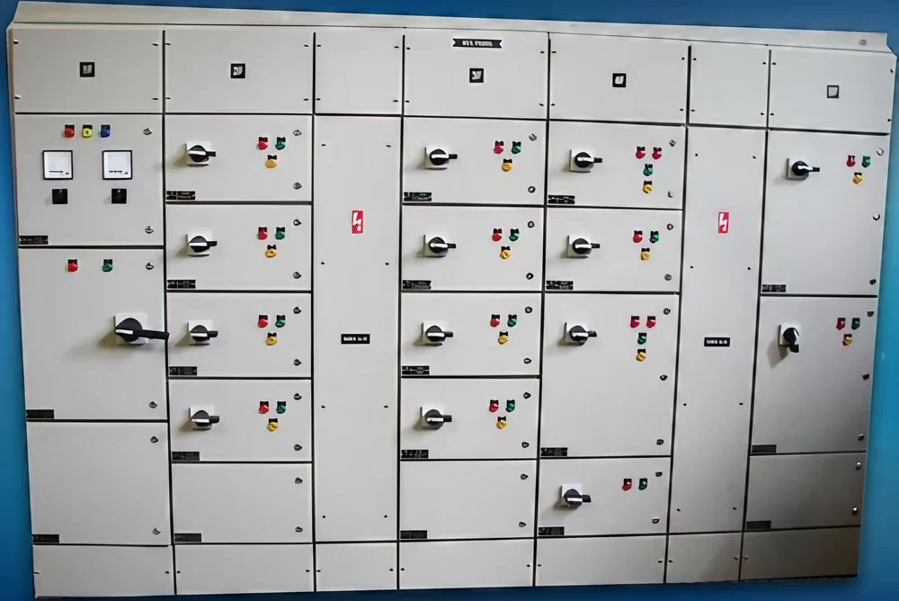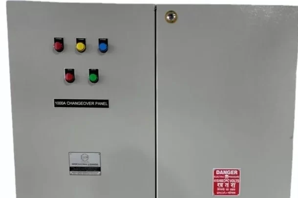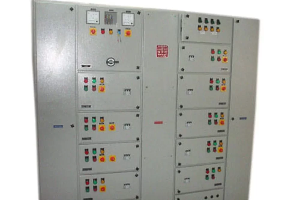
Synchronizing Panel
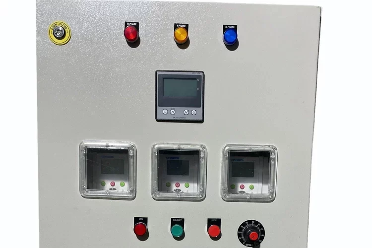
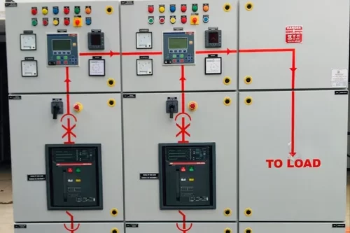
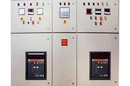
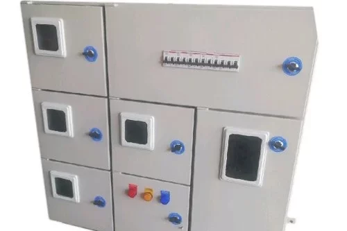
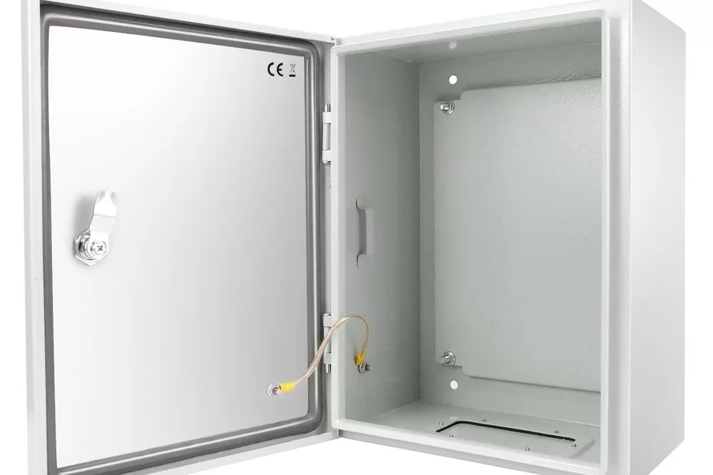
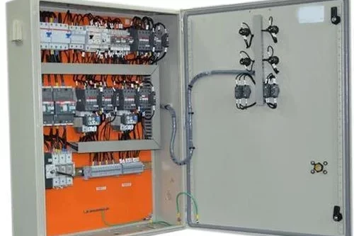
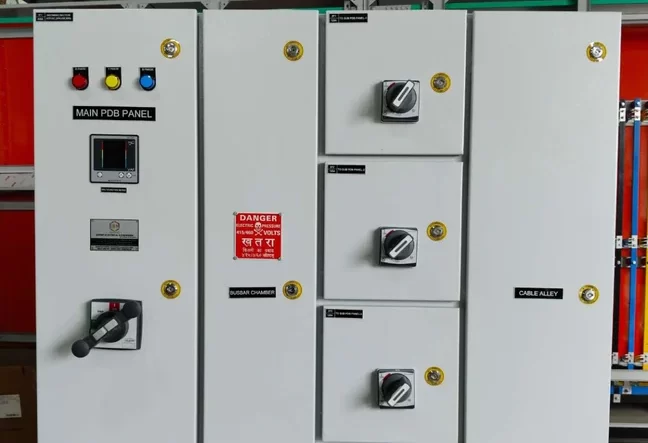
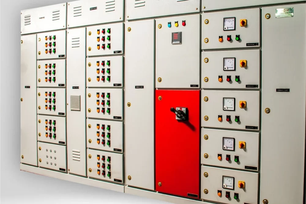
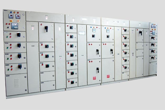
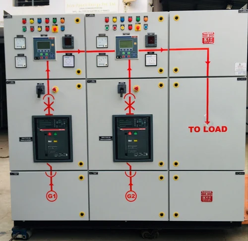
A Synchronizing Panel is a specialized electrical panel used to coordinate and manage the operation of multiple generators or power sources in parallel. This panel ensures that these power sources work together seamlessly and provide a stable and reliable power supply. Synchronizing panels are crucial in applications where continuous power is essential, such as in data centers, hospitals, industrial plants, and large commercial buildings. Here’s a detailed explanation of the synchronizing panel and its components:
Key Features of a Synchronizing Panel:
1.Synchronization:
Purpose: Ensures that multiple generators or power sources operate in sync, matching their voltage, frequency, and phase.
Function: Adjusts the output of each generator to align with the others before connecting them to the load, preventing power surges or electrical faults.
2.Load Sharing:
Purpose: Distributes the electrical load evenly among multiple generators or power sources.
Function: Balances the load to prevent overloading any single generator, extending the life of each unit and improving overall system reliability.
3.Automatic Transfer:
Purpose: Automatically transfers the load from one generator to another in the event of a failure or maintenance.
Function: Ensures continuous power supply by switching to an available generator without interrupting the power to critical systems.
4.Protection:
Purpose: Provides protection against electrical faults and abnormal operating conditions.
Function: Includes features such as overload protection, short-circuit protection, and isolation of faulty generators to safeguard the system.
5.Control and Monitoring:
Purpose: Provides centralized control and monitoring of the generators and power sources.
Function: Allows operators to monitor performance parameters, control the operation of the generators, and make adjustments as needed.
In a Synchronizing Panel, various electrical abbreviations and symbols are used to represent components, functions, and control elements. Here’s a comprehensive list of common abbreviations and symbols found in synchronizing panels:
SYNC – Synchronization
Function: Refers to the process of aligning multiple generators or power sources in terms of voltage, frequency, and phase before connecting them to the load.
AVR – Automatic Voltage Regulator
Function: Regulates the output voltage of each generator to maintain a stable voltage level across the system.
FRC – Frequency Regulator Controller
Function: Manages the generator’s speed to match the frequency of other generators.
PSM – Phase Sequence Monitor
Function: Ensures that the phase sequence of the generators matches before synchronization.
LSC – Load Sharing Controller
Function: Distributes the electrical load evenly among multiple generators to prevent overloading.
ATS – Automatic Transfer Switch
Function: Automatically switches the load between different power sources or generators based on pre-set conditions.
CT – Current Transformer
Function: Measures the current flowing through the circuit and provides a scaled-down signal for monitoring and control.
PT – Potential Transformer
Function: Measures the voltage in the circuit and provides a scaled-down signal for monitoring and control.
RTD – Resistance Temperature Detector
Function: Measures the temperature of the generator or surrounding environment.
CB – Circuit Breaker
Function: Provides protection against overcurrent and short-circuit conditions in the circuit.
MCCB – Molded Case Circuit Breaker
Function: Protects electrical circuits from overloads and short circuits.
RCD – Residual Current Device
Function: Detects earth faults and disconnects the circuit to prevent electric shock.
HMI – Human-Machine Interface
Function: Provides a user interface for interacting with the synchronizing panel, including configuration and monitoring.
PLC – Programmable Logic Controller
Function: Manages and automates the synchronization process based on programmed logic.
SCADA – Supervisory Control and Data Acquisition
Function: A system for real-time monitoring and control of the synchronizing panel through a centralized interface.
GCB – Generator Circuit Breaker
Function: A circuit breaker specifically used for protection of generators.
1.Synchronization Controller Symbol:
Symbol: Typically represented by a rectangle or box with the label “SYNC” or an icon depicting a controller.
Function: Manages the synchronization process for the generators.
2.Automatic Voltage Regulator (AVR) Symbol:
Symbol: A rectangle with the letters “AVR” or an icon depicting a voltage regulator.
Function: Regulates the output voltage of the generator.
3.Frequency Controller Symbol:
Symbol: A rectangle with the letters “FRC” or an icon depicting a frequency regulator.
Function: Controls the frequency of the generator to match other units.
4.Phase Sequence Monitor Symbol:
Symbol: A rectangle with the letters “PSM” or an icon depicting a phase monitor.
Function: Monitors and ensures correct phase sequence.
5.Load Sharing Controller Symbol:
Symbol: A rectangle with the letters “LSC” or an icon depicting load distribution.
Function: Manages the distribution of load among generators.
6.Automatic Transfer Switch (ATS) Symbol:
Symbol: A rectangle or switch icon with the letters “ATS.”
Function: Automatically switches the load between power sources.
7.Current Transformer (CT) Symbol:
Symbol: A circle with a line passing through it or a rectangle with the letters “CT.”
Function: Measures current and provides a scaled-down signal.
8.Potential Transformer (PT) Symbol:
Symbol: A rectangle or circle with the letters “PT.”
Function: Measures voltage and provides a scaled-down signal.
9.Resistance Temperature Detector (RTD) Symbol:
Symbol: A rectangle or circle with the letters “RTD” or a thermometer icon.
Function: Measures temperature.
10.Circuit Breaker (CB) Symbol:
Symbol: A rectangle or square with the letters “CB” inside.
Function: Provides overcurrent protection.
11.Generator Circuit Breaker (GCB) Symbol:
Symbol: A rectangle with the letters “GCB” or an icon depicting a generator.
Function: Protects generators from electrical faults.
12.Residual Current Device (RCD) Symbol:
Symbol: A rectangle with the letters “RCD” or a standard RCD icon.
Function: Detects earth faults and prevents electric shock.
13.Human-Machine Interface (HMI) Symbol:
Symbol: A screen or panel icon with the letters “HMI.”
Function: Provides a user interface for monitoring and control.
14.Programmable Logic Controller (PLC) Symbol:
Symbol: A rectangle with the letters “PLC” or an icon depicting a logic controller.
Function: Manages and automates control processes.
15.Supervisory Control and Data Acquisition (SCADA) Symbol:
Symbol: A rectangle or screen icon with the letters “SCADA.”
Function: Centralized system for monitoring and control.
16.Alarm Symbol:
Symbol: A triangle with an exclamation mark or a bell icon.
Function: Indicates an alarm or fault condition.
17.Indicator Light Symbol:
Symbol: A circle or square with a lightbulb icon.
Function: Represents an indicator light showing the status of the system.
18.Emergency Stop Symbol:
Symbol: A red button icon with “E-STOP” or similar marking.
Function: Provides an emergency shutdown option.
A Synchronizing Panel is essential in managing and coordinating multiple power sources, particularly generators, to ensure a stable and reliable power supply. Here’s a detailed overview of the uses and applications of a synchronizing panel:
1. Parallel Operation of Generators:
Purpose: Enables multiple generators to operate in parallel, ensuring that their outputs are synchronized in terms of voltage, frequency, and phase.
Use: Useful in settings where continuous power is critical and multiple generators are required to handle varying loads or provide redundancy.
2. Load Sharing:
Purpose: Distributes the electrical load evenly among the generators.
Use: Prevents any single generator from being overloaded, thus extending the life of each unit and improving overall system reliability and efficiency.
3. Automatic Load Transfer:
Purpose: Automatically transfers the load between different power sources in case of a generator failure or maintenance.
Use: Ensures uninterrupted power supply by switching to an available generator without affecting the connected load.
4. Power Redundancy:
Purpose: Provides backup power to critical systems.
Use: Ensures continuous operation of essential services such as data centers, hospitals, and industrial processes in case of primary power source failure.
5. Seamless Integration with Utility Power:
Purpose: Allows for synchronization with the main utility power grid.
Use: Facilitates the transition between generator power and utility power, ensuring a stable and uninterrupted power supply.
6. Emergency Power Supply:
Purpose: Ensures a reliable backup power source during emergencies or power outages.
Use: Provides emergency power to critical infrastructure and systems, such as fire alarm systems, emergency lighting, and medical equipment.
7. Improved Efficiency:
Purpose: Optimizes the operation of generators by balancing the load and running them at their most efficient operating points.
Use: Reduces fuel consumption and operating costs by ensuring that generators are used efficiently.
8. Maintenance Flexibility:
Purpose: Allows for the maintenance of individual generators without interrupting power to the load.
Use: Facilitates scheduled maintenance and repairs by enabling the removal of one generator from service while others continue to operate.
9. System Protection:
Purpose: Protects generators and associated equipment from electrical faults and abnormal operating conditions.
Use: Includes features such as overcurrent protection, short-circuit protection, and isolation of faulty generators to safeguard the system.
10. Real-Time Monitoring and Control:
Purpose: Provides centralized monitoring and control of multiple generators and power sources.
Use: Allows operators to monitor performance parameters, control generator operation, and make adjustments as needed from a central location.
11. Remote Monitoring and Management:
Purpose: Enables remote access and management of the synchronizing panel.
Use: Allows operators to monitor and control generators and power sources from a remote location, enhancing operational flexibility and response times.
12. Integration with Automation Systems:
Purpose: Integrates with other control systems, such as PLCs and SCADA systems, for coordinated operation.
Use: Facilitates automation of complex power management tasks, providing centralized control and monitoring capabilities.
13. Power Quality Management:
Purpose: Ensures that power quality is maintained across the system.
Use: Addresses issues related to voltage fluctuations, frequency deviations, and phase imbalances, improving the overall reliability and stability of the power supply.
14. Customized Operating Modes:
Purpose: Provides flexibility in operational settings and control strategies.
Use: Allows for customization of operating modes based on specific application requirements, such as peak shaving, load shedding, or standby operation.
15. Reduced Operational Downtime:
Purpose: Minimizes downtime by providing a reliable and redundant power supply.
Use: Ensures continuous operation of critical systems and processes, reducing the risk of outages and disruptions.

